Introduction
Many types of gauge are available for measurement of pressure. The simplest form being a manometer tube, in which the rise of level of a liquid indicates the static head, this being converted to pressure by multiplying by the liquid density. An example of a much more sophisticated instrument is a pressure transducer, in which the pressure is used to deflect a diaphragm. The deflection causes an electrical signal to be generated by some means such as a electric resistance strain gauge, and this signal is displayed, typically in digital form, as the corresponding pressure. The response is rapid, being typically 1ms, and the display can be remote from the point of measurement. The Bourdon gauge (named after its inventor Eugene Bourdon) uses the deflection of a tube of oval cross-section to cause a pointer to move over a scale. Its response time is therefore long, being of the order of 1 second. Nevertheless, the Bourdon gauge is widely used in engineering practice.
All pressure gauges, of whatever type, need to be calibrated. If the required accuracy is low, then a standard calibration obtained from a sample of the particular model will suffice. For higher accuracy, a manufacturer will take special care, and will supply a calibration certificate for an individual gauge. As the calibration may change over a period, repeat calibrations may well be needed from time to time. For the highest accuracy, transducers and gauges are sometimes calibrated before each use.
The normal calibration procedure is to load the gauge with known pressures, using a dead weight tester using oil. The present experiment, however, works satisfactorily with water instead of oil.
Objective(s) of the Experiment
The test is carried out in order to calibrate a pressure gauge using a dead tester.
Equipments and Materials Needed
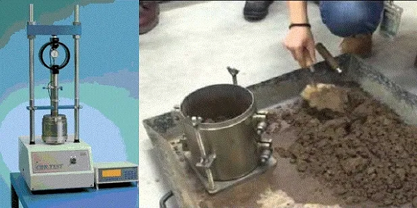
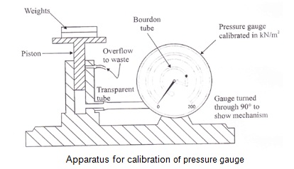
The Bourdon pressure gauge shown in the figure below has a transparent dial through which the construction may be viewed. It consists essentially of a thin-walled tube of oval cross-section, which is bent to a circular arc encompassing approximately 270′. It is rigidly held at one end, while the pressure is admitted. The other end is free to move and is sealed. When pressure is applied, the tube tends to straighten, so that the free end moves slightly. This movement operates a mechanism which drives a pointer round the graduated dial, the movement of the pointer being proportional to the applied pressure. The construction of the dead weight tester is also shown in the figure.
A cylindrical piston, free to move vertically in a closely-fitting cylinder, is loaded with known weights. The space below the piston is filled with water’, and the pressure is transmitted by the water to the gauge under test through a transparent hose. The pressure generated by the piston is easily found in terms of the total weight supported and the cross-sectional area of the piston.
Procedures
- Note the weight of the piston, and its cross-sectional area.
- To fill the cylinder, the piston is removed, and water is poured into the cylinder until it is full to the overflow level.
- Any air trapped in the tube may be cleared by tilting and gently tapping the apparatus. In point of fact, a small amount of air left in the system will not affect the experiment, unless there is so much as to cause the piston to bottom on the base of the cylinder.
- The piston is then replaced in the cylinder and allowed to settle. A spirit level placed on the platform at the top of the pistol may be used to ensure that the cylinder stands quite vertically.
- Weights are now added in convenient increments, and at each increment, the pressure gauge reading is observed.
- A similar set of results is then taken with decreasing weights. To guard against the piston sticking in the cylinder, it is advisable to rotate the piston gently while the pressure gauge is being read.
Results and Calculations
An typical result and calculations from the calibration of a pressure gauge is shown below:
Weight of piston = 1 kgf = 9.81 N
Cross-sectional area = 333 mm2 = 0.333 x 10⁻³m2
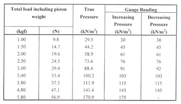
Note: The weights are converted from units of kilogram-force (kgf) to newton (N) simply by multiplying by the factor 9.81, and the true pressure follows by dividing this figure by the piston area.
For example, in the last line of the table,
True pressure = 56.9/(0.33 x10-3) = 170.9 x 10³ N/m2 = 170.9 x 10³Pa = 170.9kN/m2 = 170.9 kPa
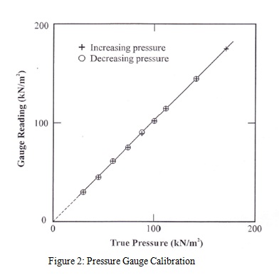
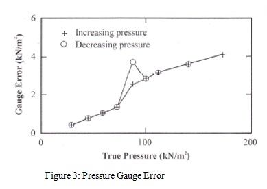
Fig 2 shows in graphical form the gauge readings in terms of true pressure, and Fig 3 shows the gauge error, again in terms of true pressure.
Discussion and Conclusion
Two different kinds of error may normally be expected in a gauge of this type. First, there is the possibility of hysteresis due to friction and backlash, so that the gauge will tend to read lower values when the pressure is increasing than when decreasing. The gauge tested here has not more than 1kN/m2 of this kind of error. Secondly, there is the graduation error due to the scale being marked off incorrectly. In this gauge, the graduation error increases fairly steadily from zero to approximately 4 kN/m2 at a reading of around 175kN/m2. This error, of about 2.3%, would be acceptable small for many engineering purposes, although Bourdon gauges with a much higher accuracy are available for accurate work.
Download “Calibration of Pressure Gauge”
Calibration-of-Pressure-Gauge-Using-Dead-Weight-Pressure-Gauge-Calibration.docx – Downloaded 0 times – 109.58 KB


")
