Introduction
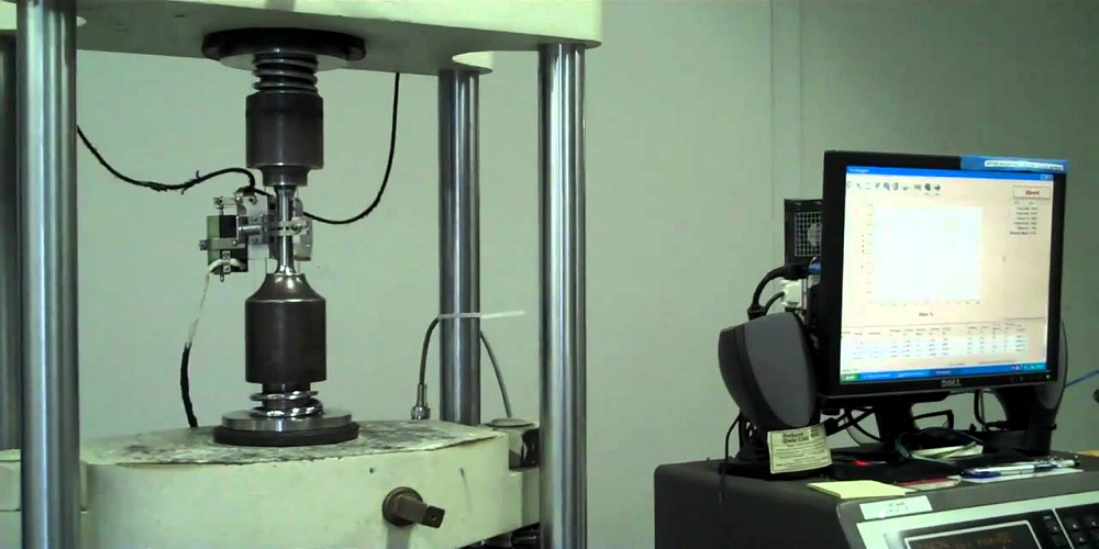
Tensile test is also known as tension test. It is considered the most fundamental type of mechanical test that can be performed on a material. Tensile tests are simple, relatively inexpensive, and fully standardized. Tensile test involves straining a test piece by tensile force, generally to fracture and it provides information on strength and ductility for metals subjected to a uniaxial tensile stress. This information may be useful in comparison of materials, alloy developments, quality control, design under certain circumstances, and detecting non-uniformity and imperfections, as indicated by the fracture surface.
Hooke’s Law
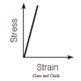
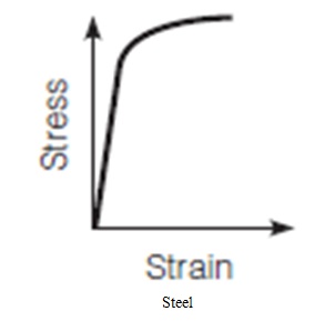
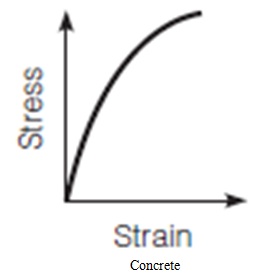
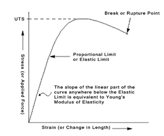
At the initial part of most tensile testing of materials, the materials exhibit a linear relationship between the applied force, or load, and the elongation of the specimen. In this linear region, the line obeys the relationship defined as “Hooke’s Law” where the ratio of stress to strain is a constant, that is, E = stress/strain (E= σ/ ε). E is the slope of the line in this region where stress (σ) is proportional to strain (ε) and is called the “Modulus of Elasticity” or “Young’s Modulus”. The figure below shows the relationship between the stress and strain of some selected materials.
Definitions
- Gauge Length (L): length of cylindrical or prismatic portion of the test piece on which elongation is measured at any moment during the test [mm]
- Original Gauge Length (Lo): Gauge length before application of force [mm]
- Final Gauge Length (Lu): Gauge length after rupture of the test piece [mm]
- Elongation: increase in the original gauge length at the end of the test
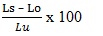
- Percentage Elongation after Fracture: permanent elongation of the gauge length after fracture. It is expressed as the percentage of the original length as
- Extension: Increase of the original length at a given moment of the test
- Percentage reduction of area: maximum change of cross sectional area, which occurred during the test, expressed as a percentage of the original cross-sectional area as

- Where Ao is the original cross-sectional area before testing [mm2]
- As is the minimum cross-sectional area after fracture [mm2]
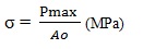
- Maximum force (Pmax): is the maximum load carried by the specimen during the tension test, N
- Tensile Strength (σ): force at any moment during the test divided by the original cross-sectional area (Ao) of the test piece:
- Engineering Strain (ε): is the change in length of the specimen divided by its original length. ε = ΔL/Lo
- Where Lo is the original length and ΔL is the change in length; ΔL = Ls – Lo
- Modulus of elasticity: E= σ / ε
- Where
- E = modulus of elasticity, MPa
- σ = stress in the proportional limit, MPa
- ε = corresponding strain, mm/mm
- Rupture strength σr = Pf / Ao
- Where
- σr = Rupture strength, MPa
- Pf = Final load, N
- Ao = cross-sectional area, mm2
Offset Method
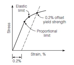
As shown in the figure below, most materials (e.g., metals and plastics) do not display an abrupt change in behavior from elastic to plastic. Rather, there is a gradual, almost imperceptible transition between the behaviors, making it difficult to locate an exact transition point. Therefore, an offset method to determine the yield strength of the material tested is allowed. In the offset method, a specified offset is measured on the abscissa as a percentage of strain, and a line with slope equal to the initial tangent modulus is drawn through this point. The point where this line intersects the stress–strain curve is the offset yield stress of the material, as seen in the Figure. Different offsets are used for different materials, and 0.2% is used for steel.
Equipments Needed
- A testing machine capable of applying tensile load at a controlled rate of deformation or load. The testing machine could be either mechanical or closed-loop electrohydraulic. The machine could be equipped with a dial gauge to indicate the load or could be connected to a chart recorder or computer to record load and deformation.
- A gripping device, used to transmit the load from the testing machine to the test specimen and to ensure axial stress within the gauge length of the specimen
- An extensometer with an LVDT or dial gauge used to measure the deformation of the specimen
- Caliper to measure the dimensions of the specimen
Procedures
- Before testing, measure diameter of the test piece; determine cross-sectional area Ao and original gauge length Lo. Mark the gauge length on the specimen, either by slight notches or with ink.
- Place the specimen in the loading machine. Ensure that test pieces are held in such a way that the force is applied as axially as possible.
- Attach the extensometer to the specimen.
- Set the load reading to zero, then apply load at a rate less than 690 kPa/min (100,000psi/min). Unless otherwise specified, any convenient speed of testing may be used up to half of the specified yield strength or yield point, or one quarter of the specified tensile strength, whichever is smaller. After the yield strength or yield point has been determined, the strain rate may be increased to a maximum of 0.5 in./in. of the gauge length per minute.
- Continue applying the load until the specimen breaks.
- Record load and deformation every 2.2 kN (500 lb) increment for steel and every 890 N (200 lb) increment for aluminum, both before and after the yield point.
Results and Calculations
- Please Check the Definition section above for reference
- Calculate the stress and strain for each load increment until failure.
- Plot the stress versus strain curve
- Determine the yield strength using the offset method or by observing the sudden increase in deformation.
- Calculate the tensile strength (σ)
- Calculate the percentage elongation. For elongation > 3.0%, fit the ends of the fractured specimen together and measure Ls as the distance between two gauge marks. For elongation <= 3.0%, fit the fractured ends together and apply an end load along the axis of the specimen sufficient to close the fractured ends together, then measure Ls as the distance between gauge marks.
- Calculate the modulus of elasticity
- Calculate the rupture strength.
- Calculate the percent reduction in cross sectional area. To calculate the cross section after rupture, fit the ends of the fractured specimen together and measure the mean diameter or width and thickness at the smallest cross section.
Conclusion
- All the quantities mentioned in the Results and Calculation section above should be reported.
- The specimen should be replaced if:
- The original specimen had a poorly machined surface
- The original specimen had wrong dimensions
- The specimen’s properties were changed because of poor machining practice.
- The fracture was outside the gauge length
- For elongation determination, the fracture was outside the middle half of the gauge length.
References
- Mamlouk, M.S. And Zaniewski J.P. (2011). ‘Materials For Civil and Construction Engineers’
- Building Materials 10 – Testing Methods. ‘Testing of Steel’
- Instron. ‘Tensile Testing’ http://www.instron.in/en-in/our-company/library/test-types/tensile-testing. Assessed on March 10, 2018.
- CE 265 Materials Lab No. 2 ‘Tensile Testing of Steel’. Fall 2004.
Download “Tensile Test on Steel”
Tensile-Test-on-Steel.docx – Downloaded 0 times – 569.38 KB")
")


